What is an Impeller
Impellers are pivotal components in modern mechanical systems, serving as the driving force behind fluid dynamics in industries such as aerospace, automotive, energy production, and manufacturing. These rotating devices convert mechanical energy into fluid motion or thrust with exceptional precision and efficiency, making them indispensable in applications ranging from pumps and compressors to turbines and renewable energy systems. This comprehensive guide explores the definition, structure, working principles, applications, design parameters, manufacturing techniques—including advanced five-axis CNC machining—maintenance strategies, and future innovations of impellers. Whether you’re an engineer, researcher, or industry professional, it provides detailed insights into the role of impellers in precision engineering.
Definition, Structure, and Working Principles of Impellers
An impeller is a rotating component designed to transfer energy between fluids and mechanical systems, forming the core of many power-driven devices. Its design and functionality make it a cornerstone of precision engineering, particularly in high-performance applications.
Definition and Historical Context: In industrial contexts, impellers have two primary definitions: first, as a wheel equipped with moving blades, often part of an impulse steam turbine rotor; second, as the collective term for a wheel and its rotating blades. The concept of impellers dates back to the Industrial Revolution, evolving from rudimentary waterwheels to sophisticated components in modern machinery. Today, they are integral to high-tech equipment like turbine machinery and aviation engines, where precision and efficiency are paramount.
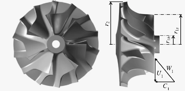
Structure of an Impeller: An impeller typically consists of a hub, blades, and sometimes a shroud. The hub connects to a shaft, providing structural support, while the blades—ranging from 4 to 12 in number—are the primary elements for energy transfer. Impellers used in high-precision applications, such as integral impellers in aviation engines, feature thin blades (top thickness as low as 0.70 mm, root thickness up to 1.63 mm), significant twist angles, and minimal spacing between blades (often less than 10 mm). Shrouds, when present, enhance structural integrity and guide fluid flow, with impeller diameters varying from 50 mm to 500 mm and widths between 20 mm and 200 mm.
Classification: Impellers are classified based on flow type: centrifugal (radial flow), axial (parallel flow), or mixed-flow (combined action). They can also be categorized as open (without a shroud) or closed (with a shroud), each suited to specific tasks. Open impellers are easier to clean, while closed impellers offer higher efficiency, achieving up to 85% in optimized designs.
Working Principles: Impellers operate on fluid dynamics principles, using rotation to generate centrifugal force and momentum transfer. As the impeller spins at speeds ranging from 1000 to 50,000 RPM, it accelerates fluid outward, converting mechanical energy into kinetic energy or pressure. Bernoulli’s principle enhances this process by facilitating pressure changes, while efficiencies can reach 75-95% depending on design. For instance, in a centrifugal pump, fluid enters the impeller, gains velocity, and exits with increased pressure, achieving flows of 50-5000 GPM and heads up to 300 meters.
Key Mechanisms: Centrifugal force drives fluid radially, while momentum transfer increases pressure, making impellers critical for high-speed operations. Energy losses, such as friction (0.5-2%) and turbulence, are minimized through precise blade design and impeller machining techniques.

Applications of Impellers Across Diverse Industries
Impellers are versatile components, integral to various industries where fluid dynamics play a crucial role. Their applications span multiple systems, enhancing efficiency and performance through tailored designs.
Pumps:
Centrifugal Pumps: Impellers in centrifugal pumps convert mechanical energy into fluid kinetic and pressure energy, rotating at 1800-3600 RPM to achieve flows of 50-5000 GPM and heads up to 300 meters. They are widely used in chemical processing (e.g., transporting acids) and urban water supply systems, with efficiencies of 75-85%.
Axial Pumps: Axial-flow impellers, featuring 4-8 blades, handle high flows (up to 10,000 GPM) at low heads (5-30 meters), ideal for agricultural irrigation and wastewater treatment, achieving efficiencies of 75-85%.
Compressors:
Centrifugal Compressors: Impellers perform multi-stage compression, rotating at 10,000-30,000 RPM to increase gas pressure up to a 10:1 ratio, with efficiencies of 80-90%. They are essential in air compression stations and natural gas pipelines, supporting industrial operations.
Screw Compressors: Impellers assist screw rotors, enhancing compression ratios (up to 8:1) and efficiencies (75-85%), commonly used in refrigeration systems and industrial gas compression.
Turbines:
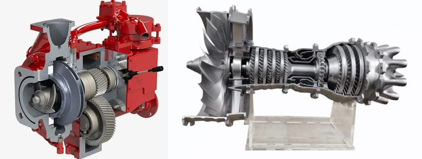
Gas Turbines: Impellers rotate at 20,000-50,000 RPM, converting high-temperature, high-pressure gas kinetic energy into mechanical energy, driving generators or aircraft engines with power outputs up to 500 MW, used in power generation and aviation.
Hydro Turbines: Impellers harness water flows of 5-50 m/s, achieving efficiencies of 90-95% with mixed-flow or axial designs, powering hydroelectric dams for renewable energy production.
Renewable Energy Systems:
Wind Turbines: Impellers with 2-3 blades (diameter 40-120 m) capture wind energy at speeds of 10-25 m/s, adjusting to 10-20 RPM for 1-5 MW output, widely used in wind farms for clean energy production.
Steam Turbines: Impellers convert steam energy (pressure 10-50 bar) into mechanical energy at 3000-6000 RPM, with efficiencies of 85-90%, supporting power plants.
Specialized Applications:
Hydraulic Systems: Impellers in hydraulic pumps and motors convert mechanical energy into hydraulic pressure (up to 3000 PSI) at 1000-3000 RPM, used in construction machinery and automation lines.
Jet Engines: Fan and turbine impellers rotate at 5000-40,000 RPM, compressing air for thrust, critical for commercial jets and fighter aircraft, with efficiencies of 80-85%.
These applications highlight the adaptability of impellers, which are tailored to meet specific operational demands through advanced engineering and impeller machining techniques.
Design Parameters, Manufacturing Techniques, and Future Innovations
Impeller performance depends on meticulously designed parameters, advanced manufacturing processes, and ongoing innovations to meet the demands of modern industries. Precision engineering, particularly through five-axis CNC machining, plays a critical role in achieving optimal results.
Design Parameters:
Geometric Parameters: Blade shapes (backward-curved, forward-curved, radial) impact efficiency (75-90%), with 6-12 blades optimizing flow (50-5000 GPM) and pressure (up to 300 meters head). Diameters range from 100-500 mm, increasing efficiency by 10-15% in hydro turbines, while blade thickness varies (top 0.70 mm, root 1.63 mm in integral impellers).
Motion Parameters: Rotational speeds of 1000-50,000 RPM affect power output (0.1-500 MW), while peripheral speeds of 20-120 m/s influence energy transfer efficiency (80-95%).
Performance Parameters: Flow rates of 50-10,000 GPM, heads of 5-300 meters, and efficiencies of 75-95% are determined by impeller design, with friction losses minimized to 0.5-2% through precise blade angles and spacing.
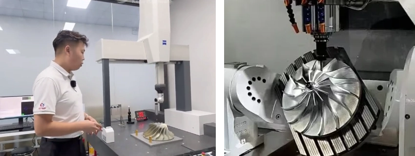
Manufacturing Techniques: Traditional methods like casting and EDM often result in defects such as porosity or sand holes, making advanced techniques like five-axis CNC machining essential for integral impellers. Five-axis machines, available in double swing table, double swing head, or single swing head/single swing table configurations, offer significant advantages: they allow multi-face machining in one setup, achieving tolerances of ±0.01 mm, and enable high-speed cutting where 70% of heat is dissipated through chips, extending tool life. Common materials include titanium TC4 (ultimate strength 895 MPa), aluminum 6061 (310 MPa), and stainless steel 304 (515 MPa), with surface finishes as low as Ra 0.4 µm. Challenges include deformation due to narrow flow channels (width<10 mm="">50 mm), and low rigidity, as well as tool breakage during corner clearing due to small tool diameters.
Optimization through Modeling: Manufacturing optimization involves creating accurate impeller models using software like Pro/E. Key steps include generating pts-format point files for blade and hub curves, fitting curves with Pro/E’s datum features, and creating surfaces via sweep blending and boundary blending. The impeller model is then arrayed rotationally (angle = 360°/number of blades), refined with variable-radius fillets, and validated through simulation to adjust tool angles and improve efficiency by 5-10%.
Precision Control: Precision in five-axis machining is ensured by setting the programming zero point at the blank surface center, using edge finders for validation, selecting tools (e.g., drills, milling cutters) with standard tool holders for rapid changes, and defining cutting parameters like back engagement (0.1-0.5 mm), feed rate (500-1500 mm/min), and spindle speed (10,000-20,000 RPM) to balance accuracy, tool life, and efficiency.
Future Innovations: The future of impellers lies in advanced manufacturing and materials. 3D printing enables complex geometries, reducing weight by 15-20%, while composite materials like carbon fiber-reinforced polymers (ultimate strength 150,000 PSI) promise efficiencies exceeding 95%. These innovations will enhance applications in renewable energy (wind turbines) and aviation (jet engines), supported by rapid prototyping and smart materials that adapt to operational conditions.
| Parameter | Range | Impact | Manufacturing Requirement |
| Blade Thickness | 0.70 mm (top) - 1.63 mm (root) | Efficiency 75-90%, Flow Stability | ±0.01 mm tolerance, Ra 0.4 µm |
| Blade Number | 4-12 | Pressure Increase 5-10%, Flow 50-5000 GPM | Five-axis CNC, 1-2 day lead time |
| Impeller Diameter | 100-500 mm | Power Output 0.1-500 MW, Efficiency +10-15% | Precision machining, 3-7 days |
| Rotational Speed | 1000-50,000 RPM | Power 0.1-500 MW, Pressure Up to 3000 PSI | High-speed cutting, ±0.01 mm |
Impellers are the heart of fluid dynamics in power systems, driving efficiency and performance across industries. Their optimal design and precise manufacturing are crucial for enhancing system capabilities, with ongoing advancements paving the way for sustainable and high-performance engineering.
Kesu specializes in manufacturing high-quality impellers using advanced machining and rapid prototyping, focusing on precision, durability, and custom solutions. Partner with the CNC factory for reliable, cost-effective impeller parts that meet stringent industry standards, delivered in 1-14 days based on volume.
Frequently Asked Questions (FAQ)
What is an impeller and its primary function?
An impeller is a rotating component that transfers energy between mechanical systems and fluids, generating pressure, flow, or thrust in devices like pumps and turbines, with efficiencies ranging from 75% to 95%.
How are impellers classified?
Impellers are classified as centrifugal, axial, or mixed-flow based on fluid dynamics, and as open or closed depending on whether they have a shroud, each suited to specific applications.
What materials are commonly used for impellers?
Common materials include titanium TC4 (ultimate strength 895 MPa), aluminum 6061 (310 MPa), and stainless steel 304 (515 MPa), chosen for durability and performance in demanding environments.
What challenges are faced in impeller manufacturing?
Challenges include deformation due to narrow flow channels (width<10 mm="">50 mm), and low rigidity, as well as tool breakage during corner clearing due to small tool diameters.
What future innovations are expected for impellers?
Future innovations include 3D printing for complex geometries, reducing weight by 15-20%, and composite materials (150,000 PSI) for efficiencies up to 95%, enhancing renewable energy and aviation applications.